In Order to Allow Communication Between Vlans for Exchange of Data, What Must Be Used?
Nosotros wrote an commodity which covers Virtual Local Area Networks (VLANs) as a concept, and another article on configuring VLANs on Cisco switches. The remaining subject to cover is the different options that exist for routing between VLANs. This is besides sometimes choseninter-vlan routing, or occasionally Router on a Stick (RoaS).
Why practise we demand Routing Between VLANs?
As we learned in a prior commodity, VLANs create a logical separation between Switch ports. Essentially, each VLAN behaves like a separate physical switch. To illustrate this, below are ii topology pictures of the same environment – one Physical and one Logical.
The Physical topology depicts a switch and four hosts in two unlike VLANs – Host A and Host B are in VLAN xx and Host C and Host D are in VLAN 30. The logical topology reflects how the physical topology operates – the ii VLANs essentially create two separate concrete switches.
Despite all four hosts existence connected to the aforementioned physical switch, the logical topology makes it clear that the hosts in VLAN xx are unable to speak with the hosts in VLAN thirty. Notice since in that location is nada connecting the 2 "virtual" switches, there is no way for Host A to speak to Host C.
Since Host A and Host C are in different VLANs, it is likewise implied that they are in different Networks. Each VLAN will typically correspond to its own IP Network. In this diagram, VLAN xx contains the x.0.twenty.0/24 network, and VLAN thirty contains the 10.0.30.0/24 network.
The purpose of a Switch is to facilitate communication within networks. This works neat for Host A trying to speak to Host B. However, if Host A is trying to speak to Host C, we will need to use some other device – one whose purpose is to facilitate communication between networks.
If y'all've read the Packet Traveling series, then you know that the device which facilitates communication between networks is a Router.
A router will perform the routing function necessary for two hosts on different networks to speak to 1 some other. In the same way, a Router is what we will need in order for hosts in different VLANs to communicate with one another.
At that place are three options available in order to enable routing between the VLANs:
- Router with a Carve up Physical Interface in each VLAN
- Router with a Sub-Interface in each VLAN
- Utilizing a Layer 3 Switch
The remainder of this article will explore these iii options and their configuration.
Router with Separate Concrete Interfaces
The simplest way to enable routing between the two VLANs to simply connect an additional port from each VLAN into a Router.

The Router doesn't know that it has two connections to the same switch — nor does information technology need to. The Router operates similar normal when routing packets between two networks.
In fact, the procedure of a packet moving from Host A to Host D in this topology will work exactly every bit it does in this video. The only difference is since there is only one physical switch, at that place will only be one MAC address table – each entry includes the mapping of switchport to MAC address, too as the VLAN ID number that port belongs to.
Each switch port in this diagram is configured as an Admission port, we tin can utilise the range command to configure multiple ports equally once:
Switch(config)# interface range eth2/0 - ii Switch(config-if-range)# switchport mode access Switch(config-if-range)# switchport admission vlan twenty Switch(config)# interface range eth3/0 - 2 Switch(config-if-range)# switchport mode admission Switch(config-if-range)# switchport access vlan 30
Of form, before assigning the switchport to a VLAN, it is a good thought to create the VLAN in the VLAN Database.
The Router interfaces also employ a standard configuration — configuring an IP address and enabling the interface:
Router(config)# interface eth0/2 Router(config-if)# ip address x.0.twenty.1 255.255.255.0 Router(config-if)# no shutdown Router(config)# interface eth0/iii Router(config-if)# ip address 10.0.xxx.1 255.255.255.0 Router(config-if)# no shutdown
Beneath you will find various show commands for the Router and the Switch, these tin be used to understand and validate how the surroundings is operation.
Router Show Commands
show run ip int brief ip road arp cdp neighbour
Router# bear witness running-config ... interface Ethernet0/ii ip address 10.0.20.1 255.255.255.0 ! interface Ethernet0/3 ip address ten.0.30.1 255.255.255.0
Router# show ip interface brief Interface IP-Address OK? Method Status Protocol ... Ethernet0/2 ten.0.20.1 YES manual up up Ethernet0/iii 10.0.30.1 Yes manual up up ...
Router# testify ip route Codes: Fifty - local, C - connected, ... Gateway of last resort is not ready 10.0.0.0/eight is variably subnetted, iv subnets, 2 masks C 10.0.xx.0/24 is directly connected, Ethernet0/2 L x.0.20.1/32 is directly connected, Ethernet0/two C ten.0.30.0/24 is directly connected, Ethernet0/three Fifty 10.0.30.1/32 is directly connected, Ethernet0/three
Router# prove arp Protocol Address Historic period (min) Hardware Addr Type Interface Internet ten.0.20.one - aabb.cc00.0220 ARPA Ethernet0/2 Cyberspace 10.0.20.11 two 0050.7966.6800 ARPA Ethernet0/2 Internet 10.0.20.22 5 0050.7966.6801 ARPA Ethernet0/2 Internet 10.0.30.1 - aabb.cc00.0230 ARPA Ethernet0/3 Internet 10.0.30.33 4 0050.7966.6802 ARPA Ethernet0/three Internet x.0.thirty.44 4 0050.7966.6803 ARPA Ethernet0/3
Router# bear witness cdp neighbors Capability Codes: R - Router, South - Switch, I - IGMP, B - Source Route Span ... Device ID Local Intrfce Holdtme Adequacy Platform Port ID Switch Eth 0/3 126 R Due south I Linux Uni Eth 3/0 Switch Eth 0/2 126 R S I Linux Uni Eth 2/0
Switch Show Commands
evidence run mac table vlan brief cdp neighbor
Switch# bear witness running-config ... vlan 20 name Ruby ! vlan 30 name Blue ... interface Ethernet2/0 switchport access vlan 20 switchport manner access ! interface Ethernet2/one switchport access vlan twenty switchport way access ! interface Ethernet2/ii switchport access vlan xx switchport mode admission ! interface Ethernet3/0 switchport admission vlan 30 switchport mode admission ! interface Ethernet3/one switchport access vlan thirty switchport mode access ! interface Ethernet3/ii switchport admission vlan 30 switchport mode access
Switch# prove mac address-table Mac Address Table ------------------------------------------- Vlan Mac Address Type Ports ---- ----------- -------- ----- xx 0050.7966.6800 DYNAMIC Et2/1 20 0050.7966.6801 DYNAMIC Et2/two 20 aabb.cc00.0220 DYNAMIC Et2/0 thirty 0050.7966.6802 DYNAMIC Et3/i 30 0050.7966.6803 DYNAMIC Et3/2 30 aabb.cc00.0230 DYNAMIC Et3/0 Full Mac Addresses for this criterion: 6
Switch# show vlan brief VLAN Name Condition Ports ---- --------------------------- --------- -------------------- ... twenty RED active Et2/0, Et2/i, Et2/2 30 BLUE active Et3/0, Et3/i, Et3/2 ...
Switch# show cdp neighbors Adequacy Codes: R - Router, S - Switch, I - IGMP, B - Source Route Span ... Device ID Local Intrfce Holdtme Capability Platform Port ID Router Eth 3/0 152 R B Linux Uni Eth 0/3 Router Eth ii/0 166 R B Linux Uni Eth 0/2
Router with Sub-Interfaces
The previously described method is functional, simply scales poorly. If there were five VLANs on the switch, then we would need 5 switchports and five router ports to enable routing between all five VLANs
Instead, there exists a way for multiple VLANs to stop on a single router interface. That method is to create a Sub-Interface.
 A Sub-Interface allows a single Physical interface to be divide into multiple virtual sub-interfaces , each of which terminate their ain VLAN.
Sub-interfaces to a Router are similar to what Trunk ports are to a Switch – one link conveying traffic for multiple VLANs. Hence, each router Sub-interface must also add a VLAN tag to all traffic leaving said interface.
The logical operation of the Sub-interface topology works exactly equally the carve up physical interface topology in the section earlier information technology. The only deviation is with Sub-interfaces, only 1 Router interface is required to terminate all VLANs.
Go along in mind, still, that the drawback with all VLANs terminating on a single Router interface is an increased risk of congestion on the link.
The Sub-interface feature is sometimes referred to asRouter on a Stick or One-armed Router. This is in reference to the single router terminating the traffic from each VLAN.
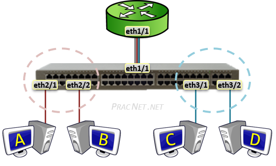
The Switch's port facing the router is configured every bit a standard Trunk:
Switch(config)# interface eth1/1 Switch(config-if)# switchport trunk encapsulation dot1q Switch(config-if)# switchport manner body
The Router's configuration of Sub-interfaces is fairly direct forward. Get-go, nosotros enable the concrete interface:
Router(config)# interface eth1/i Router(config-if)# no shutdown
Side by side, we create and configure the first Sub-interface:
Router(config)# interface eth1/1.20 Router(config-subif)# encapsulation dot1Q 20 Router(config-subif)# ip address 10.0.20.1 255.255.255.0
Autonomously from using the Sub-interface distinguisher (eth1/1.20) and using the encapsulation dot1q <VLAN#> control, the residual of the interface configuration is exactly the same equally any other regular physical interface.
Similarly, nosotros will also configure the Sub-interface for VLAN 30:
Router(config)# interface eth1/1.30 Router(config-subif)# encapsulation dot1Q 30 Router(config-subif)# ip address 10.0.30.1 255.255.255.0
A point of clarity regarding the Sub-interface syntax. The number after the concrete interface (fa0/3.twenty and fa0/iii.xxx) only serves the purpose of splitting up the physical interfaces into Sub-interfaces. The number specified in the encapsulation dot1q vlan ## command is what actually specifies what VLAN ID# the traffic belongs to.
These two values do not take to friction match, simply often they do for the purpose of technician sanity.
Below you lot will find various testify commands for the Router and the Switch. These tin be used to sympathize and validate how the environs is performance.
Router Sub-Interface Testify Commands
prove run ip int brief ip route arp cdp neighbor
Router# evidence running-config ... interface Ethernet1/1 no ip address ! interface Ethernet1/1.20 encapsulation dot1Q twenty ip address 10.0.xx.i 255.255.255.0 ! interface Ethernet1/ane.30 encapsulation dot1Q 30 ip address 10.0.30.i 255.255.255.0
Router# bear witness ip interface brief Interface IP-Address OK? Method Condition Protocol ... Ethernet1/1 unassigned YES NVRAM up up Ethernet1/i.twenty 10.0.20.1 YES manual up upwardly Ethernet1/1.30 10.0.30.1 Yep manual upward upward ...
Router# show ip route Codes: L - local, C - connected, ... Gateway of final resort is not set ten.0.0.0/8 is variably subnetted, iv subnets, ii masks C x.0.twenty.0/24 is directly connected, Ethernet1/1.20 L 10.0.twenty.ane/32 is directly connected, Ethernet1/1.20 C ten.0.30.0/24 is straight connected, Ethernet1/one.thirty L 10.0.30.ane/32 is directly connected, Ethernet1/1.30
Router# show arp Protocol Address Age (min) Hardware Addr Type Interface Internet 10.0.twenty.1 - aabb.cc00.0211 ARPA Ethernet1/1.20 Cyberspace 10.0.20.11 0 0050.7966.6800 ARPA Ethernet1/1.twenty Internet 10.0.20.22 0 0050.7966.6801 ARPA Ethernet1/i.twenty Net 10.0.xxx.1 - aabb.cc00.0211 ARPA Ethernet1/1.30 Internet 10.0.30.33 0 0050.7966.6802 ARPA Ethernet1/1.30 Net ten.0.30.44 0 0050.7966.6803 ARPA Ethernet1/1.30
Router# show cdp neighbors Adequacy Codes: R - Router, S - Switch, I - IGMP, B - Source Route Bridge ... Device ID Local Intrfce Holdtme Capability Platform Port ID Switch Eth ane/1 150 R Due south I Linux Uni Eth 1/i
Switch Body Show Commands
evidence run mac tabular array vlan brief int trunk cdp
Switch# prove running-config ... vlan 20 name Red ! vlan 30 proper name BLUE ... interface Ethernet1/one switchport trunk encapsulation dot1q switchport mode body ! interface Ethernet2/1 switchport admission vlan 20 switchport mode access ! interface Ethernet2/2 switchport access vlan 20 switchport mode access ! interface Ethernet3/ane switchport admission vlan 30 switchport manner access ! interface Ethernet3/2 switchport access vlan thirty switchport mode access
Switch# show mac address-table Mac Address Tabular array ------------------------------------------- Vlan Mac Address Blazon Ports ---- ----------- -------- ----- 1 aabb.cc00.0211 DYNAMIC Et1/1 twenty aabb.cc00.0211 DYNAMIC Et1/1 30 aabb.cc00.0211 DYNAMIC Et1/1 20 0050.7966.6800 DYNAMIC Et2/one twenty 0050.7966.6801 DYNAMIC Et2/two xxx 0050.7966.6802 DYNAMIC Et3/one 30 0050.7966.6803 DYNAMIC Et3/2 Full Mac Addresses for this criterion: vii
Switch# prove vlan brief VLAN Name Status Ports ---- --------------------------- --------- ------------------- ... 20 RED agile Et2/ane, Et2/ii 30 Blueish active Et3/one, Et3/2 ...
Switch# show interfaces trunk Port Mode Encapsulation Condition Native vlan Et1/1 on 802.1q trunking i Port Vlans immune on trunk Et1/one 1-4094 Port Vlans allowed and agile in management domain Et1/1 1,twenty,30 Port Vlans in spanning tree forwarding state and non pruned Et1/one 1,20,xxx
Switch# show cdp neighbors Capability Codes: R - Router, S - Switch, I - IGMP, B - Source Road Bridge ... Device ID Local Intrfce Holdtme Capability Platform Port ID Router Eth 1/i 136 R B Linux Uni Eth one/1
Layer 3 Switch
The last option for routing between VLANs does non involve a router at all. Nor does it involve using a traditional switch.
Instead, a unlike device entirely can be used. This device is known as a Layer 3 Switch (or sometimes also as a Multilayer switch). But exactly what is a Layer 3 switch?
 A Layer 3 Switch is dissimilar from a traditional Layer 2 Switch in that it has the functionality for routing between VLANs intrinsically. In fact, when because how a L3 Switch operates, yous tin can safely imagine that a Layer three Switch is a traditional switch with a built in Router.
With regard to VLANs the Multilayer switch is configured mostly the same way as a regular L2 switch:
MultilayerSwitch(config)# vlan 20 MultilayerSwitch(config-vlan)# name Red MultilayerSwitch(config)# vlan thirty MultilayerSwitch(config-vlan)# name BLUE MultilayerSwitch(config)# interface range eth2/0 - 2 MultilayerSwitch(config-if-range)# switchport manner access MultilayerSwitch(config-if-range)# switchport access vlan 20 MultilayerSwitch(config)# interface range eth3/0 - ii MultilayerSwitch(config-if-range)# switchport mode access MultilayerSwitch(config-if-range)# switchport access vlan 30
Then, for each VLAN that you desire the Multilayer switch to route for, you have the option of configuring an IP address inside what is known as an SVI, or a Switched Fiveirtual Interface.
AnSVI serves as the L3 termination point for each VLAN – aka, the way in or out of each VLAN. Some other way of looking at it is that the SVI serves as the interface on the congenital-in Router of the Multilayer switch, assuasive traffic from 1 VLAN to reach the built-in Router and be routed to some other VLAN as necessary.
The configuration for an SVI involves two parts. First, enabling IP Routing; and 2nd, applying an IP address to the VLAN.
To enable IP Routing, apply the following control:
MultilayerSwitch(config)# ip routing
IP Routing only needs to be enabled once. Some L3 switches come with it enabled past default. Applying the control while it is already enabled will not crusade any damage, so if in doubt equally to whether information technology is already enabled or non, just applying information technology again is safe.
To apply an IP accost to the VLANs, configure the SVI as follows:
MultilayerSwitch(config)# interface vlan 20 MultilayerSwitch(config-if)# ip address 10.0.xx.1 255.255.255.0 MultilayerSwitch(config-if)# no shutdown MultilayerSwitch(config)# interface vlan 30 MultilayerSwitch(config-if)# ip address 10.0.30.1 255.255.255.0 MultilayerSwitch(config-if)# no shutdown
The two configurations above will enable routing between VLAN xx and VLAN 30. The hosts in each VLAN can use the IP addresses 10.0.twenty.ane and 10.0.30.1 equally their default gateway (respectively).
When Host A sends a packet to Host B, the package volition exist switched within the same VLAN – no L3 processing will occur.
When Host A sends a packet to Host C, the bundle will exist sent to the SVI to be routed to the other VLAN – all regular L3 processing will occur: the TTL will exist decremented and the L2 header volition be rewritten.
Multilayer Switch Configuration
evidence run mac address-table vlan cursory
MultilayerSwitch# evidence running-config ... ip routing ... interface Vlan20 ip address 10.0.xx.one 255.255.255.0 ! interface Vlan30 ip address 10.0.30.i 255.255.255.0
MultilayerSwitch# show mac accost-table Mac Accost Table ------------------------------------------- Vlan Mac Address Blazon Ports ---- ----------- -------- ----- xx 0050.7966.6800 DYNAMIC Et2/1 20 0050.7966.6801 DYNAMIC Et2/ii 30 0050.7966.6802 DYNAMIC Et3/2 xxx 0050.7966.6803 DYNAMIC Et3/1 Total Mac Addresses for this criterion: four
MultilayerSwitch# bear witness vlan brief VLAN Proper name Condition Ports ---- --------------------------- --------- ------------------- ... xx RED active Et2/1, Et2/2 30 Blue agile Et3/1, Et3/2
ip route arp ip int brief
MultilayerSwitch# testify ip route Codes: Fifty - local, C – continued, ... Gateway of last resort is non fix 10.0.0.0/viii is variably subnetted, 4 subnets, 2 masks C ten.0.xx.0/24 is directly connected, Vlan20 L ten.0.20.1/32 is directly continued, Vlan20 C 10.0.xxx.0/24 is straight connected, Vlan30 Fifty ten.0.30.1/32 is directly connected, Vlan30
MultilayerSwitch# show arp Protocol Address Age (min) Hardware Addr Type Interface Net x.0.xx.1 - aabb.cc80.0200 ARPA Vlan20 Cyberspace ten.0.20.11 0 0050.7966.6800 ARPA Vlan20 Net 10.0.20.22 0 0050.7966.6801 ARPA Vlan20 Internet x.0.thirty.ane - aabb.cc80.0200 ARPA Vlan30 Internet 10.0.xxx.33 0 0050.7966.6803 ARPA Vlan30 Internet 10.0.30.44 0 0050.7966.6802 ARPA Vlan30
MultilayerSwitch# show ip interface cursory Interface IP-Address OK? Method Status Protocol ... Ethernet2/i unassigned Yeah unset upward upward Ethernet2/2 unassigned YES unset up upward ... Ethernet3/i unassigned YES unset upwards up Ethernet3/ii unassigned YES unset up upwards ... Vlan20 10.0.20.i Yep manual up up Vlan30 10.0.thirty.one YES manual up upwards
Annotation: both sets of tabs and configuration in a higher place are from the same device. For the sake of organization, one set of tabs refer to the L3 functions and the other refers to the L2 functions.
Summary
This article discussed the iii dissimilar options for Routing between VLANs. In each case, the hosts in advice comport exactly the same. In fact, the hosts have no visibility into how and what they are connected to.
Each strategy higher up has its own benefits and limitations. Hopefully at this bespeak you lot have a good idea of the options bachelor to enable advice between hosts on dissimilar VLANs.
Source: https://www.practicalnetworking.net/stand-alone/routing-between-vlans/
Post a Comment for "In Order to Allow Communication Between Vlans for Exchange of Data, What Must Be Used?"